PCB prepreg is a partially cured resin and reinforcement sheet which is used to join cores when a multilayer board is laminated. Used often as a gluing in teams. That shortcut is hiding the real operation that the sheet is doing: Resin system, glass style, resin content and resin flow determine the thickness of the dielectric, the capacity of holding the impedance, the ability to create voids and the warpage of the panel after press.
No standard catalog number exists for prepreg thickness and the two pieces of the same type of prepreg in the press are not identical. The thickness of the laminate depends on the press profile, number of plies, and the amount of resin used. If you are creating controlled-impedance or high-reliability multilayers, those variables are not considered in the stack-up discussion at the end of the first impedance miss.
What Exactly Is Prepreg in a PCB Stack-Up?
Finished board can have same dielectric for Core and Prepreg. They are not of the same material class, nor in the same state when entering the press. Early recognition of the distinction will help to avoid the deterioration of lamination notes, impedance models and layer spacing.
Prepreg vs Core: Different Roles in the Same Multilayer
A pre-made laminated core is already cured. It normally features a copper layer on one or both sides and is delivered as a stable dielectric block whose thickness is mostly determined prior to the bookings. Cores are used for inner layer circuits, for placement of reference planes and for providing rigid predictable dielectric sections in the stack.
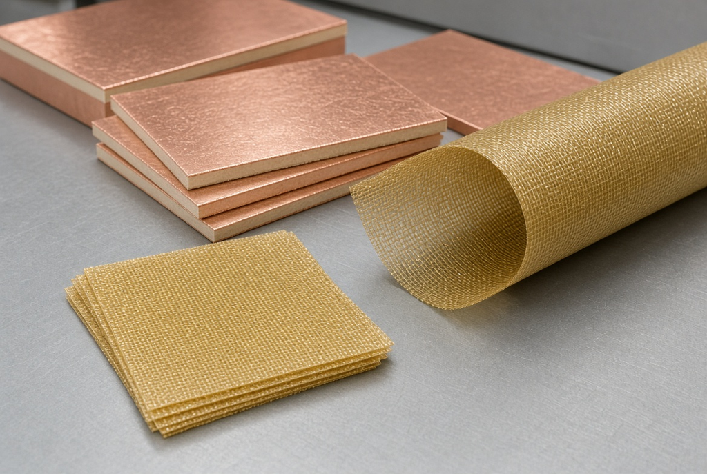
Contrary is the opposite state of prepreg. It is a B stage sheet, that is, a sheet which is coated with resin and is not yet fully cured but still can be handled and cut. Does not contain Cu. It will soften during use in the press, flow, wet copper and laminate surfaces and it will cure into the bond line between cores. Cores are the blocks that you can’t change. With prepreg you can get that bond and thickness between those blocks that you haven’t gotten yet.
This is why there is an incomplete stack up drawing in this division, where the “dielectric 0.1 mm.” is the only thing included, since there are yet to be decided which of the dielectrics are to be cores and which are to be prepreg plies that will move with heat and pressure.
Where Prepreg Appears in Typical Multilayer Constructions
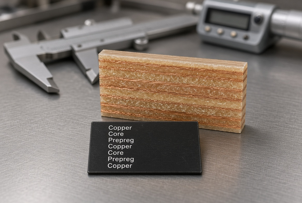
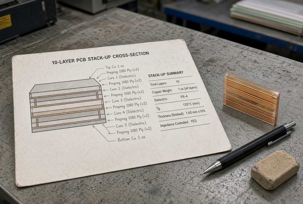
Most rigid multilayers have prepreg between the pairs of inner layers (core, prepreg, core, prepreg etc.) and outer foils on the outside. If greater thickness is desired than the cores can provide, additional plies are added to achieve the desired final thickness. It is not required that the spacing after lamination be the same as the drawing, but it is important that the tight impedance layers be adjacent to one or more prepregs that are set to have the appropriate spacing to match the model spacing.
Prepreg also fills very tight gaps that cores do not fill, such as around etched copper, the edge of inner features and between minor mismatches of surfaces. It is not the materials themselves that are “real” after they have been selected that are considered “filler”. One key part of it is that which makes a high-layer-count/mixed-signal stack buildable.
Prepreg Materials and Construction
However, if you’re asking yourself, “what is PCB prepreg,” it’s only half of the answer! Resin sheet composed of resin, reinforcement and target resin. Any other change of those would also change the lamination behavior.
Resin Systems Used in PCB Prepreg
Most commercial multilayer applications are done using the standard epoxy systems. When the board will end up in more thermal stress during assembly or in the field, high-Tg epoxy grades are selected. When insertion loss or high frequency resins are more important than commodity cost, low insertion loss or high frequency resins are used. Standard epoxies are not the choice for constructions that require a higher temperature.
The type of resin used will affect glass transition behavior, loss, and aging of the sheet over a number of heat cycles. Does NOT specify the final dielectric thickness alone. Epoxy prepregs can be of the same family, but differ in thickness when pressed because of the various glass styles that they use and because of the different resin content. Make sure that core and prepreg are compatible families so that the stack does not add electrical and thermal properties that the model did not consider.
Don’t give a brand or shop-floor designation to the fabrication notes until the fabricator has a look at the stack. The input that is useful is the performance target: Tg range, loss class, thermal demand, and standard digital, mixed-signal, and/or high-temperature construction.
Reinforcement Styles and Resin Content
Most frequently, the reinforcement is woven glass from which the sheet is taken and that plays a significant role in the mechanical strength and largely in the dielectric properties. The amount of resin in the sheet and how the sheet will be compressed in the press will be dependent on style (woven construction and thickness).
Most teams have not utilized the lever that is resin content. Resin content of the sheet is the more the sheet will flow under pressure and make it thinner. A less sticky sheet flows less, and has a thicker thickness of the sheet coming in. When filling around copper this can be helpful. It is a problem if the assumption is made that the impedance layer is the one that was demonstrated, and not the one that was pressed.
In the case of prepreg materials in PCB applications, the construction is style plus resin-content intent and is not a single nickname that is simply copied from a vendor table. The nickname is a first description or nickname. The value of the design is the pressed value.
Key Properties of Prepreg That Designers Should Understand
The properties which alter a drawing are not the ones that look great on a cover of a datasheet. The ones that are reported in impedance reports and warped panels are resin flow, gel time, pressed thickness, dielectric constant, loss and thermal expansion.
Resin Flow, Gel Time, and Thickness After Lamination
The resin flow is a measure of the ease and distance that the softened resin flows without gelling. That time period is called gel time. Once the resin becomes gel, the thickness is set and it cannot be adjusted. When a press profile is too fast or too slow or too incompatible with the sheet, there are situations where residual resin can be left in the wrong place, either with starved bond lines in one area, or thick resin pockets in another.
Therefore, the thickness of prepreg is not actually a part number in a PCB stack up, but is a result. The outcome is transferred by the incoming thickness, the resin content, number of plies, copper topography, the press cycle. “1080 class” sheet on a drawing is an expectation, not a commitment, for the spacing applied to a field solver.
If the stack is impedance-controlled, ask the fabricator to develop the model of the dielectrics made up of the combination being pressed. The most common cause for a clean stack-up to become a revision is to consider the thickness of the catalog as the finished thickness.
Dielectric Constant, Loss, and Thermal Behavior
Prepreg is used to contribute to the stack’s effective Dk and Df in the same way as core but not the same. The dielectric that the signal traverses depends on the thickness of the glass, the amount of resin and how the ply is compressed. Thermal expansion and Tg is dependent upon resin system and reinforcement, and can be the first moving layer during reflow or thermal cycling if there is a mismatched prepreg in a well laid-up stack.
The rule of thumb that is often used is that the core and prepreg are from the same material family, and the data obtained from the prepreg is from the fabricator’s characterized data for the impedance model. Generally, all FR-4 with a Dk of 4.5 will be included within the “FR-4 Dk = 4.5” value, hiding the resin-rich prepreg from the glass-heavy core. The properties of the prepreg material in the MLB are only beneficial when the boards are pressed as-built, not a number off a blog table.
How Prepreg Enables and Constrains Multilayer Lamination
The prepreg lamination function is a simple one to describe, but hard to execute – Flow, wet, fill and cure the prepreg to a void free bond without breaking the required thickness of the electrical design.
Bonding Cores and Filling Voids
Pressing prepreg in the press requires the prepreg to be wet to copper and laminate faces, to navigate into etched recesses and then to stop. To fill these pockets and minimize the amount of air trapped, the flow has to be good. The delamination risk, CAF paths or poor bonding within the inner layers are results of the voids or starved areas that are caused by a weak flow, contaminated surfaces, or poor early gelled cycle.
The higher the degree of filling, the more copper will be used in the form of weight and the thicker the uneven residual copper and thin dielectrics and the less amount of resin. A high layer count, high density of inner conductors on a board will need a greater quantity of resin in the spaces between layers. Each individual ply of prepreg might be chosen for a final thickness rather than for fill, and a perfect drawing might result in an inadequate final thickness at the bond line.
Process Control on Fabricator side: Cleanliness, Lay-up discipline, Vacuum, Heat ramp and pressure. Be sure it’s on your side: Do not specify a dielectric that is so thin that no combination of qualified prepreg and copper will be able to fill and hold spacing, or a copper distribution that is so uneven that no prepreg will be able to fill and hold spacing.
Thickness Tuning, Symmetry, and Warpage Control
The overall thickness and the balance of the stack around the centerline are targeted by engineers using prepreg type and ply count. That is legitimate. The loading of prepreg one side to “make thickness” and the other side to “lean” or the use of heavy copper on one side and resin rich prepreg on the other side with no mechanical offset is a warpage problem.
Incoming inspection is not always carried out. Typically happens after reflow when the board is free to move. Implement the prepreg as a mechanical solution: use as many plies on the midplane as possible (if possible); consider copper distribution; and don’t trim away any excess prepreg thickness at the outer layers.
Common Pitfalls When Specifying or Relying on Prepreg
Most prepreg problems are spec problems in new programs and not “mystery chemistry. The same 3 problems are present on impedance controlled digital boards, mixed signal stacks and high layer count backplanes.
Treating Prepreg Thickness as a Fixed Design Parameter
The first-article impedance is already wagering on a number that the press wouldn’t get precisely if it is simply a prepreg thickness offered by the catalog line. Typical symptoms include a change in the impedance of the system, or a late change in the width of the trace, or a fabricator who wishes to change a trace that appeared to be locked.
Use target pressed dielectric and allowed tolerance to build the model, and then let the fabricator propose the appropriate ply mix for the model to meet the requirements. The targets for electrical and mechanical should be recorded on the drawing. The shop should have the combination that suits them.
Ignoring Resin Content and Flow in High-Layer-Count or Thin-Dielectric Designs
Thin dielectrics, tall stacks increase the resin content and flow. Low amount of resin filling of the copper topography when making a request for very small layer spacing. If you have lots and lots of layers, then you are adding the risk to lots and lots of interfaces. This can result in out-of-spec impedance, local thin spots or a closed bond line with local voids in the product area.
If a tight spacing is required, indicate this as a requirement and inquire if a single ply, two thinner plies or another resin-content grade would provide a safer fill path. Know that the thinnest incoming thickness is not necessarily the most manufactureable.
Over-Constraining Prepreg Types Without Fabricator Input
This can be prevented if the fabricator chooses to use a particular prepreg designation that has been qualified for an old project in a post that is discussed in a forum or a material brochure. The availability models, press characterization and impedance models are related to the materials produced by the shop. They might have to build a sub-optimal structure or materials conversation may be extended due to a designation they do not use.
Provide impedances, complete thickness, thermal class and any reliability comments. Allow the fabricator to plot them on to prepreg types that are known to them. Don’t do the mapping and then edit it!Edit before you map up!
Practical Guidance for Working With Prepreg in Stack-Up Design
The best method for selecting prepreg using controlled impedance is to refrain from using a part number.
Start From Impedance and Thickness Targets, Not Prepreg Part Numbers
Document number of layers, impedance controlled layers, target impedances, and finished board thickness and mechanical constraints such as warpage or stiffness. These are design needs. Prepreg style, resin content and ply count answer to those requirements in the manufacturing.
If it has been used by a previous board, then use it as a suggestion, not a rule. Another ply mix might be needed for the next stack to fit the electric window, maintaining the fill and spacing.
Use the Fabricator’s Standard Prepreg Options as a Starting Point
A few prepreg types and ply combinations have been tested by most fabricators, and they have experience with the press behavior and impedance of these prepreg materials. Start there. Those combinations flow and they’re known to be paired with cores carried.The combinations are known to flow and known to be paired to the cores carried.
Customize where it is needed: A loss class that the standard set can’t deliver, a thickness that the standard ply-mix can’t cover, even a thermal demand that’s not in the normal epoxy window. There are no default options for custom material. It needs to be for some reason, which the standard doesn’t give.
Summary Guidance – Treat Prepreg as a Strategic Material, Not Just Glue
The prepreg is the sheet that gives rise to a multilayer. It will help to bond cores, large percentage of the dielectric thickness, affect the impedance, void risk, warpage and long term reliability. The only thing that’s still moving in this press is glue – and that thing that goes out of control in calling it glue is glue.
Include prepreg type and ply count in early stack-up, next to impedance and thickness targets. Follow up with the fabricator to verify fill, flow, symmetry and where they can press the material. The goal is to have an electrically clean, but laminable, stack. What looks like a correct stack in incoming thickness table is not.