The majority of delays in rapid PCB prototyping begin prior to the writing of a traveler. While the circuit may be electrically correct and the copper may appear clean in the viewer, the build is still waiting because there is no drill data or an undefined build-up, notes conflict, or finish and test requirements are not specified for the fabricator. The questions are pricey on the schedule even when the design is not the issue.
Gerbers are not a production-ready package. A package can start includes complete copper, mask and legend data, matching drill and slot files, a fabrication drawing that includes stack-up, thickness, copper weight and finish, and one controlling revision. It is intended for designers, NPI engineers and hardware teams who require this package in place before requesting a fast first article.
What “Rapid PCB Prototyping” Really Requires From Your Data
A thin file set is not manufacturable if it is requested for a “quick turn. The speed of rapid PCB prototype fabrication is the clarity; all the layers the shop requires are included, the hole information is correct, the drawing names the construction, rather than relying on habits. Engineering has to temporarily halt and introspect, yes until those pieces sit together.
Complete copper, mask, legend, and outline data
Save the entire layer set in a single format (Gerber, ODB++, IPC-2581) and do not change the name of the layers on the drawing. Not just top and bottom copper, but inner and outer copper, solder mask, legend and defined board outline. If a layer is missing or corrupted, a hold is forced: the fabricator is unable to determine if a mask opening was intended or if the inner plane is missing or incomplete or if the outline exists in a mechanical layer that did not ship.
A common error is making the assumption that mask and legend are somehow “standard”, and excluding them from the zip. They are not an accessory that could be added or removed at will. The area for soldering is controlled by the mask openings. The assembly team identifies the board by using the legend text. If a layer is not supposed to be used, indicate this on the drawing. If there is no sound on the file, it is a partial export.
Drill, slot, and hole definitions that match the copper
The NC drill files, hole table and slot definitions must correspond to the copper pads and annular rings to which they relate. The difference between plated and non-plated holes, slot widths, tool dimensions and keep out around slots should be clearly defined. When drill and copper clash the shop can’t get going because it doesn’t know which file is the Master File, if a hole is a via or a mounting hole, or what width a routed slot should end at.
Avoid placing hole intent just in a CAD plot file that is never removed from the design folder. The hole table on the fabrication drawing to be included in the same package as the copper and the drill file. It is important to note that finished hole tolerances are dependent on the design and the process of the fabricator, and cannot be assumed to be the same. If a slot or an unplated hole is load-bearing or alignment critical then make it part of the drawing, rather than assuming the default tool table is close enough.
Fabrication drawing with stack-up, thickness, and finish
The document that pulls all of the data together is the fabrication drawing. It should specify the number of layers, the manner in which the layers are stacked, final thickness, copper weight, surface finish and any special notes that cannot be conveyed on the Gerbers. In case there are impedance layers, their names and the names of the targets should be indicated in the drawing or on an attached stack-up table. If the board is not impedance controlled, make sure to mention that too, so they don’t make up a coupon.
A common source for the wrong construction is to only include critical requirements in the email itself, not the drawing, and leave the drawing without anything in it or to be generic. Emails age. Readme files are separated from zip. The drawing is carried by the work. Lock the construction in place prior to the quote being released.
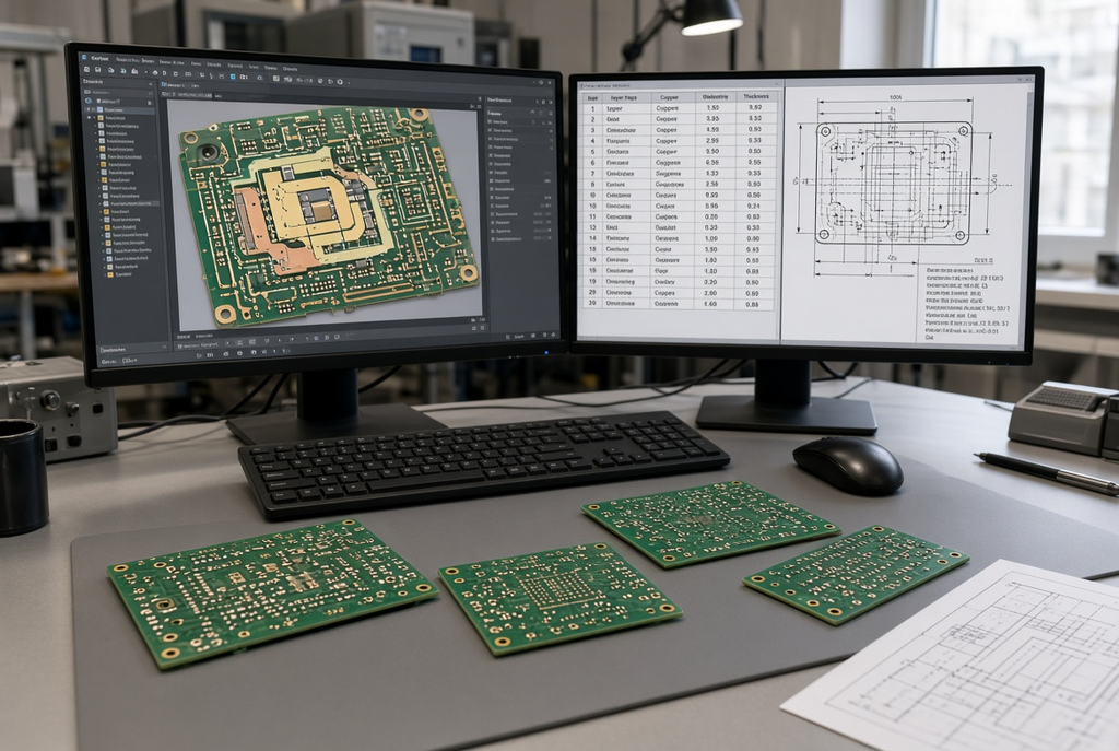
DFM and Design Decisions That Affect Prototype Speed
The job is sent into review when the file is complete. The number of questions following is determined by the design choices. DFM for first prototype is not a slogan. A set of decisions made in the construction which either allow the shop to run with a known process or require additional planning.
Layer count, via structure, and impedance control
Typically, it’s easier to prototype a board quickly using a through-hole multilayer board with the traditional multi-layer stack-up than it is to prototype a design that requires sequential lamination, dense HDI, or blind/buried vias. The more via structures there are, the more process steps and verification. That doesn’t mean these constructions are incorrect. It means that they must be planned, written down and agreed on in the prototype plan, not found in CAM.
Impedance control also performs its own tests: stack-up agreement, coupon or test intent, and that the named dielectric and copper weight are acceptable for the target. If the first article is just proving fit and connectivity, then try to think about whether this revision needs controlled impedance. The ability to build the layers, based on type, and to construct the impedance relies on the design of the structure and on the capability of the fabricator. A previous vendor’s limits are not necessarily universal.
Trace, spacing, annular ring, and copper-to-edge clearances
The most frequent engineering notes that an ordinary prototype generates are: Tight trace and spacing, small annular ring, and crowded copper to the edge of the board. They aren’t always pushing the features to the extreme and it doesn’t necessarily involve scrapping the board. It does increase the likelihood of a question, a requested change, or a process note that was not a part of the original schedule.
The conservative clearances are typically the quicker route for a first prototype, unless a product absolutely must operate with the tighter clearances. If you need to go tight, mark it on the drawing and realize that it will take longer for the review. This is where a “simple” four-layer board becomes a correspondence thread – leaving a minimum feature buried in CAD defaults with no note.
Panelization and delivery format for prototypes
Handling and test access as well as any future assembly step will be influenced by delivery format. With prototypes, simplicity can be the best approach: one board or just a handful that are easily separated and probed. When trying to design a first article production style panel (density of tabs, scoring tightness, and lack of handling rails when the board is small), depaneling and bench work can be more difficult than the electrical design.
Indicate if single boards are desired or an array and if there is any need for a rail, fiducial, or tooling hole for the fixture designed by yourself. Even if you have no plan of assembly, don’t make a complicated panel “for later.” Panelization of a later revision may be done after circuit has been proven.
Common File and Design Pitfalls That Delay Prototypes
The reason why the stall prototype files for PCB’s are not particularly unusual. They are unfulfilled promises, contradictory versions and comments that are open to interpretation. All can be prevented with a brief review of the inside.
Incomplete or conflicting revision information
A last week’s Gerbers, this morning’s drawing and a stack-up dating last month is not a package. It is a debate. Common causes: Fabricator CAM’s an older copper set and the drawing has been changed to Rev C when it is referring to Rev A in the set. Fabricator drawing Rev C and the drill file has Rev A in the header. The build is in doubt as to which document will be used for controlling the build, which the shop must ask.
Have a revision on each document in the release and indicate on the drawing the master document set. If a late copper fix has been issued after the drawing, then update the drawing or freeze the copper. Don’t send both and trust that the latter time will be the winning one.
Vague or generic notes that invite interpretation
Words like “standard fabrication,” “typical tolerance” or “impedance as required” do not constitute actionable notes. One reader will be using common FR-4 stack and HASL. The other one will take on high-Tg material and ENIG. A third will add the impedance coupons you were never expecting! This leads to an unexpected construction, the target impedance is not met, or there’s a test gap that only shows up once the boards have arrived.
Use specific language instead of general or use a reference to an attached stack-up, finish callout or test note. If a parameter actually has no influence on this prototype, record not controlled on this revision. This is better said than to be silent and make it “standard”.
Late changes to material, thickness, or finish
Late swap is NOT a 1-line edit, once a quote and a traveler are created for a named laminate family, finished thickness and surface finish. It can affect available materials, planning, chemistry of surface preparation, and testing or assembly of the board. The changes are not to be done after the job is on the queue, but before it is released for production.
If you have no choice, consider it a new release: “Drawing changed”, “Revision changed”, and a clear indication of what has been substituted with the previous callout. Two documents battle on the shop floor with a “make it ENIG instead” chat message.
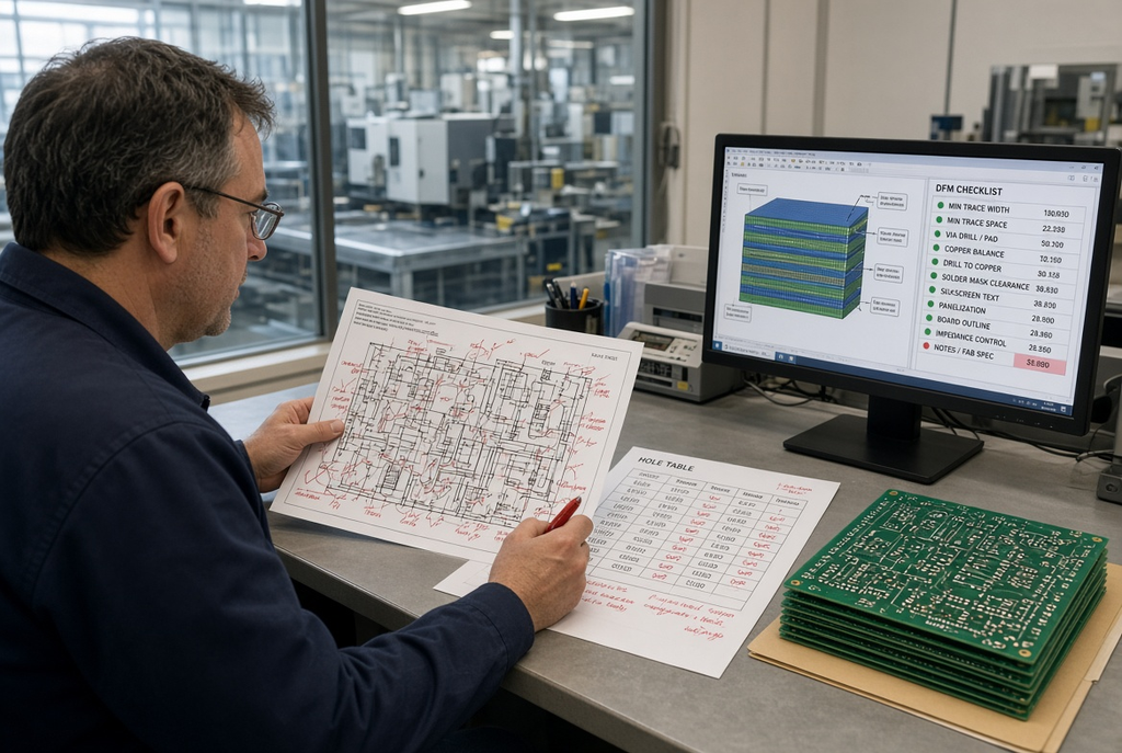
A Pre-Submission Checklist for Rapid PCB Prototypes
Most of the holds above are avoided if you pass the internal pass short before asking for the build. Use it as a pre-flight list, not as additional paperwork.
Data-package completeness checks
Prior to leaving your team, verify:
- All copper, solder mask, legend and board outline done in a consistent style
- The data in the NC drill and slot should be identical to the copper and the hole table.
- A fabrication drawing with a statement of stack up, finished thickness, copper weight, surface finish and special notes.
- Every file is subject to one current revision, and has a controlling document.
- Explicit statement that impedance is not controlled or specification of the impedances they are named for.
- Any test, marking or delivery format instruction, not just for the email, but for the drawing as well.
In the absence of any item, the package is not ready. It’s much quicker to fix it on your desk than to have to answer the same gap once CAM has opened the job.
Internal DFM and risk review
On the same day the files are zipped, conduct a design side review:
- Measure width and spacing against requirement for this revision
- Ring shape covering on holes that are drilled into components
- The clearance between the copper and the edge of the board, as well as between the mask and the edge of the board.
- Via structure: Via structure – via only, via in a pad, via in blind, via in buried
- Impedance layers and targets (if any)
- Panel or single-board delivery – any fixture or test access that you are already familiar with that you need
If the product can be simplified, do so in a construction sense in a first article. Prove the circuit on a build the shop can make without any extra process invention, then if the design still needs these features add HDI, exotic materials or tight features to a later revision. The best way to avoid having PCB prototype delays unrelated to the netlist.
Making PCB for quick prototyping is not really about squeezing production dates, but it’s about getting the production-ready Gerbers and the drawing and drill data that make Gerbers usable. The first article on the path you thought you bought is the one you get when you have a PCB prototype DFM checklist on your side.
Frequently Asked Questions
What files are needed for rapid PCB prototyping?
The following is required: complete PCB prototype data package (copper, mask, legend, outline, and NC drill and slot files), a fabrication drawing that includes stack up, finished thickness, copper weight, surface finish and special notes. There should be only one revision controlling the entire set. If you are ordering an array, a panel drawing is a nice optional extra, if you are ordering an impedance table, that will help, and if you have a readme that tells where to find the drawing, then that will help as well, but only if it’s consistent with that set.
Are Gerber files enough to start a prototype build?
Not by themselves. The production-ready PCB Gerbers are required, but the shop also requires drill data that matches the copper and a drawing with construction and finish names. Gerbers describe artwork. They don’t, in isolation, tell you how thick the item is, if it’s a laminate, or if holes are plated or not, or what revision it’s from.
How can I avoid delays in my PCB prototype order?
Submit a fully formulated one-revision package. Clear stack-up, thickness and finish prior to release. Use callouts instead of “standard” notes. Maintain consistency of late copper edits and drawing updates. Do a short pass on trace, spacing, annular ring and via structure to avoid any first engineering surprises.
What DFM checks matter most before submitting a prototype?
The most common reasons for a first article check to fail include missing layers, incorrect drill-to-copper alignment, tight annular ring, copper too near the edge, undocumented blind or buried vias, and having a named impedance that is not listed on the drawing.
Should I use complex via structures in a first prototype?
Unless the product can be validated without them. The time required for process and review is increased by Blind via, buried via, sequential lamination and high density HDI. A multilayer board with a through via is typically the quicker option to prove connectivity and fit. If the design has gained the right to the more complex structure, add it.
When should I lock stack-up, thickness, and finish for a prototype?
Lock them before they are considered released for manufacture. A change is a new plan after the quote and traveler has been created around a named construction. If you’re still selecting the finish or thickness, you’re not in rapid release yet; you’re still in design.