A multilayer, high-speed board frequently has a plated through-hole via that may extend through more layers than are required by the signal itself. The unused barrel is a via stub. In this scenario, that stub can reflect energy and consume the channel budget at typical SerDes data rates and tight differential pairs. Backdrilling with PCBs is a secondary drill (controlled) which is done for a reason and it removes part of the unused plated barrel and therefore the stub is shorter. It does or doesn’t help, depending on how stack up, layer transitions, and controlling the depth are done, not on a rule that “high speed = backdrill.”
Backdrilling does not solve all the via issues. A shorter stub length can be achieved without a second drill by using microvias, blind vias, and improved layer transition designs. The method is also time-consuming, cumbersome, and risky if depths or sides are not known. It should be used when simulation or experience in a channel indicates that the stub is truly limiting the channel.
What Is a Via Stub and Why Does It Affect Signal Integrity?
A via is more than a connection you wanted. For a through-hole stack it is a plated barrel which typically extends the entire depth of the board. When designing a PCB via, high-speed designs can’t ignore that barrel as it is a part of the channel and not a free PCB via.
How a through-hole via creates a stub in multilayer stacks
Let’s take an example of a differential pair, the vias are drilled and plated from the top to the bottom with the differential pair residing on the inner layer. The signal is emitted from the inner layer of the barrel. The rest of the lower transition is unused copper and dielectric. The left-over part is the stub.
The electrical connection remains functional at low speeds and at DC. The additional barrel still exists, dangling off the active path. At higher frequencies it acts as a short stub of transmission line: energy couples in, reflects back and goes back to where it came from. The later errors that show up in eye diagrams and compliance plots are that we assumed “the via is connected, so the leftover barrel does nothing”.
This geometry is used on backplane board, thick multilayer stacks and any geometry that calls for a through via from an outer layer to a mid-stack layer. Stub length is determined by the number of unused layers at the end of the used layers, plus the thickness of the unused dielectric material. Before discussing a second drill, the length of the stub will be determined by the rules of layer assignment and transition planning.
Stub length, resonance, and high-speed performance
The longer the stub the less often will the unused barrel be a problem. It increases the insertion loss, reduces the return loss and decreases the channel margin for connectors, packages, and routing. When that becomes a concern is not only about the label “high speed,” it depends on the data rate, encoding, equalization, and the rest of the budget, too.
There is no single “magic” number of the length of the stubs that can be used for all designs. A short unused piece of the low speed link can be hidden. A dense SerDes channel is one where the same length can be the difference between an A1 article and a respined stack. That’s why stub impact is not a rule-of-thumb used on the shop floor but should be simulated in channel or found in a measured reference design.
Consider layer transition, resonance and stub length together. Asking the pair if they need to change layers, what layers will they change to, how far the unused barrel will run and if a different transition or via type would leave a lesser amount of unused barrel is a good way to get the discussion started.
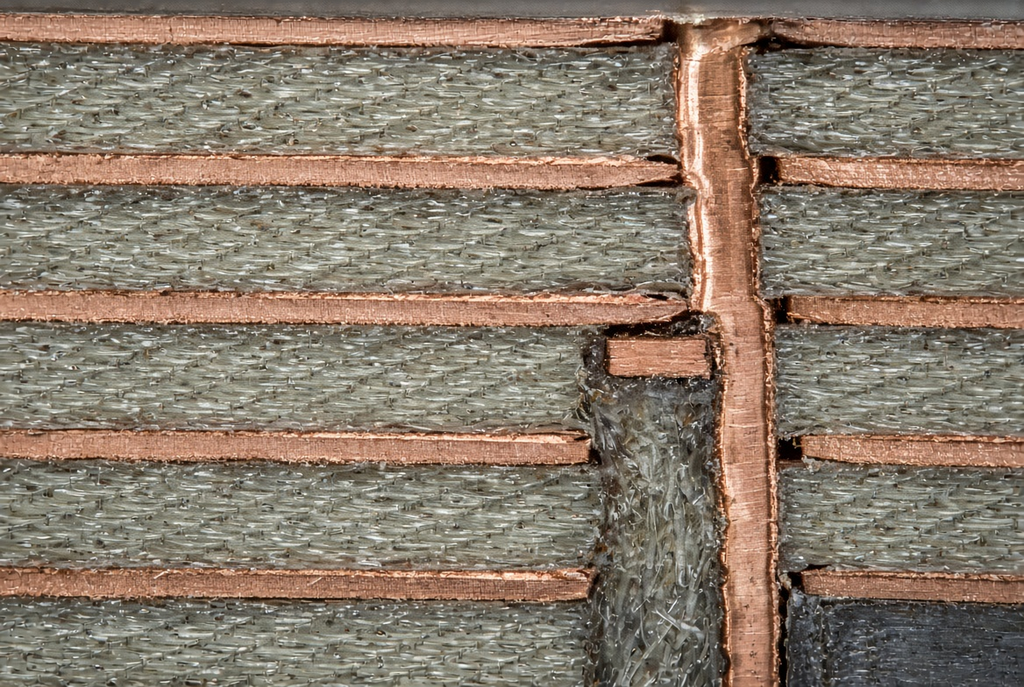
How PCB Backdrilling Removes Via Stubs
The removal of stubs by backdrilling is a production step, not a clean up after the stack has been locked. After the through-hole is drilled and plated, a larger bit is driven from one side of the board to machine away copper and dielectric in the unused portion of the barrel. The drill will stop just before the final layer where the via is still to be drilled.
The backdrill operation in the fabrication flow
The series is simple. The full through via is created by primary drill and primary plating. The secondary tool, the defined side and the target depth (or target layer), and the keep-out relative to the remaining structure are all defined for backdrill, which is then performed as a controlled-depth drilling PCB work. This leaves an open cavity instead of the barrel, with a small length of plating integrated above the working area.
The second drill must be included in the drill data from the beginning and must be included in the fabrication notes from the beginning. Conflicting files come about when the shops receive the “please backdrill the high-speed vias” after the stack-up, impedance callouts and primary drill program are all released. The scope of the depth, side and which holes will be included should be the same as the rest of the fabrication package.
Residual stub, drill tolerance, and layer transitions
Backdrill does not completely empty the barrel until the level is reached mathematically at zero. A residual stub PCB feature is left at the bottom of the backdrill and towards the target signal layer. That leftover length is determined by the gap that the Shop can stop without cutting the used Pad, the reference Pad in adjacent to it, or the dielectric that remains to be used to hold the structure.
The depth can be made as deep as the drill tolerance, layer registration and keep-out to adjacent copper will allow. While the residual might be tight on the paper, the stack has to be able to hold registration or the keep-out has to not cross a plane that the impedance model thinks is intact. Residual stub is not a one-size-fits-all rule, but a design and capabilities discussion.
Post second drill transition layer is still applicable. If the signal is already in a lot of unused layers, backdrill can shorten the stub. If there’s a channel left that is already short, the second drill might cost but have no effect on the channel.
When to Use Backdrilling in High-Speed Designs
A single tool for targeted usage is backdrilling for signal integrity. Not all via of all “fast” boards have it as their default process. The question that has to be asked is whether this un-used barrel is actually the bottle neck for the link at the rate and budget you’re working at?
Data rates, channel budget, and simulation-driven decisions
Backdrill is generally considered when the via stub eating margin is measured at the target rate in a simulation or previous spin, or in a measured reference channel. That evidence may take the form of insertion-loss shape or of a resonance located within the Nyquist region, or of a compliance plot which only recovers upon shortening the stub.
It’s not a cost-effective solution to add backdrill to all the vias “just in case.” This results in no benefit of additional drill programs, tighter documentation, or opportunities for a wrong side or wrong depth error when the stubs were never the limiter. If the unused barrel is not in the path of the spec, keep the via as a normal through-hole in the channel budget.
Stack-up and layer-transition planning as an alternative or complement
The second drill may be just as effective as the stack-up. High-speed layers can be placed at a reduced distance from one another, the number of times a pair of layers must change layers can be reduced, and having microvias or blind vias for the transitions that would otherwise leave a long unused barrel can shrink the stub before it even gets to the fabrication facility to be drilled out again.
When those decisions are made, multilayered PCB backdrill is best. The second drill then will reduce the unused barrel length on the remaining vias that need to jump additional layers. When you try to solve the backdrill problem by using a substitute for stack-up planning, you have a drawing with lots of depths and the channel will not look like the backdrill problem was solved.
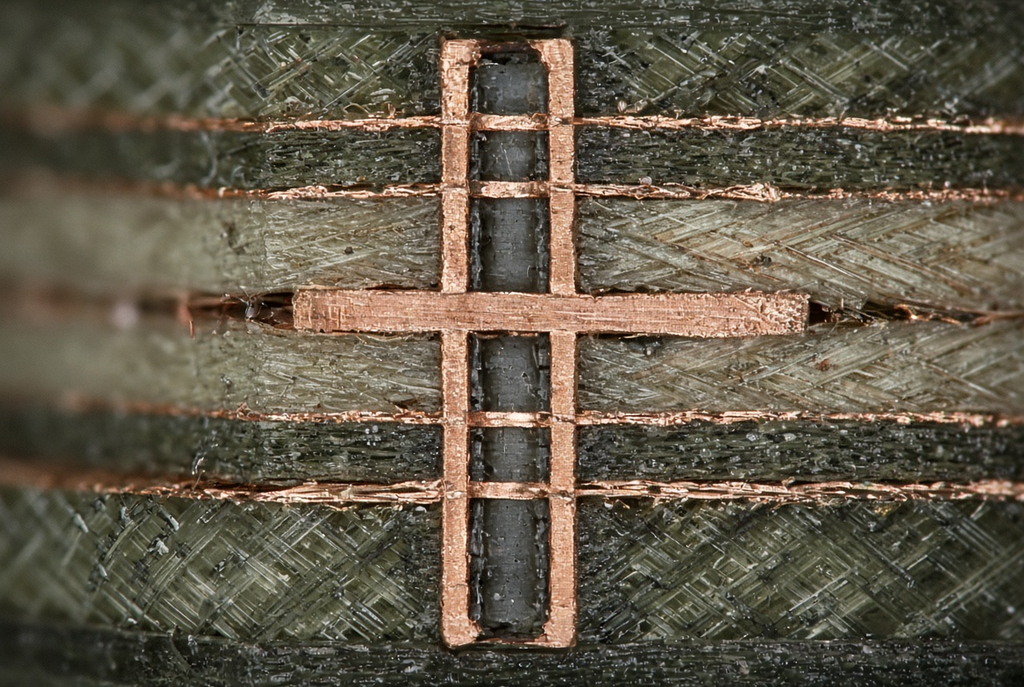
Design Rules and Documentation for Backdrill
Ultimately, backdrill design rules reside in the package that the shop is actually going to produce: drawing notes, drill or backdrill files, and the stack-up, which still matches the impedance model. If not, the hole will be drilled according to the guess of the three.
Which vias to backdrill and from which side
Drawing or drill data should specify the name of the vias, the top/bottom side of the drawing (or depth in the drill) that the secondary tool should be positioned on and to which layer or depth. A note of just “backdrill high-speed vias” does not convey to a programmer what holes, what side, or where to stop.
Get nets or via groups that require the process, and when a stop is called as a layer, not an informal word. If only some holes in a via cluster are in scope, then the file must indicate that. Side errors are often seen when the unused barrel is at the bottom of the stack, without the note stating so.
Depth control, keep-out, and reference-plane protection
The difference between a shortened stub and a damaged reference plane represents the depth control. There must be sufficient keepout for the remaining pads, nearby planes and impedance copper to remain undamaged by the secondary drill. If the cross-section is cut, the return path which is still used, or the values entered for the calculation of the impedance will be different from what the designer intended.
Coordinate depths with the stack-up. The target layer, the unused run and planes needing to survive the cavity should be in one review rather than one in a backdrill note following impedance signing. Numbers from another board should not be considered a replacement for a review. Both keep-out and residual stub rely on the stack in front of the machine, as well as what the fabricator can hold.
Drawing notes, drill files, and revision control
Record the requirement in the fabrication drawing and in the drill data, or in a separate backdrill drawing that is part of the same revision. When drawing and the drill data have conflicting notes, that can be a common cause for wrong cavities and extra engineering loops.
Ensure that drawing, stack-up, primary drill and backdrill data are all exported together into the CAD system. If a pair or a layer is moved or a change is made in the layer assignment, the backdrill table must be moved along with it. If you miss a callout, it’s just as bad if someone else did it and it’s still left out.
Common Pitfalls in Backdrill Specification and Use
The vast majority of backdrill issues are specification related. The process is known. The files are not typically so.
Backdrilling without a clear signal-integrity reason
If the process is distributed among large via populations with no channel reason, the cost and the cycle time increase but the eye diagram is not affected. We did not have a situation where the unused barrels were the limiting factor, it was connectors, length mismatch or a poorly placed transition.
Focus on the vias identified as questionable in simulation and/or measurement. Keep all the other rest standard through holes. If the only reason is “this board is high speed” stop and ask what kinds of nets, what kinds of transitions, and what does the budget actually indicate?
Unclear depths and side indicators in the fabrication package
Missing side and depth force the shop to ask or to guess. The guessing creates a cavity from a wrong face or a stop with too much stub or too close to the used layer. This is eliminated by explicit layer references, a backdrill table, and a layer-pair callout.
If a table is used, include via group, entry side, target layer and note of keep-out per line. Avoid repeating the same information in a paragraph that a program will not interpret two times.
Ignoring the impact on impedance and reference planes
An aggressive depth can intrude into a reference plane or alter the nature of the copper around a controlled-impedance pair. The unused barrel is vanished, the local stack that the field sees is not the same as the stack in the impedance note.
Check return current depths on return current containing layers and on impedance construction. Wherever a plane needs to be continuous, it can’t get this copper. This change in the pair’s reference should be reflected in the model prior to tape-out, not first article.
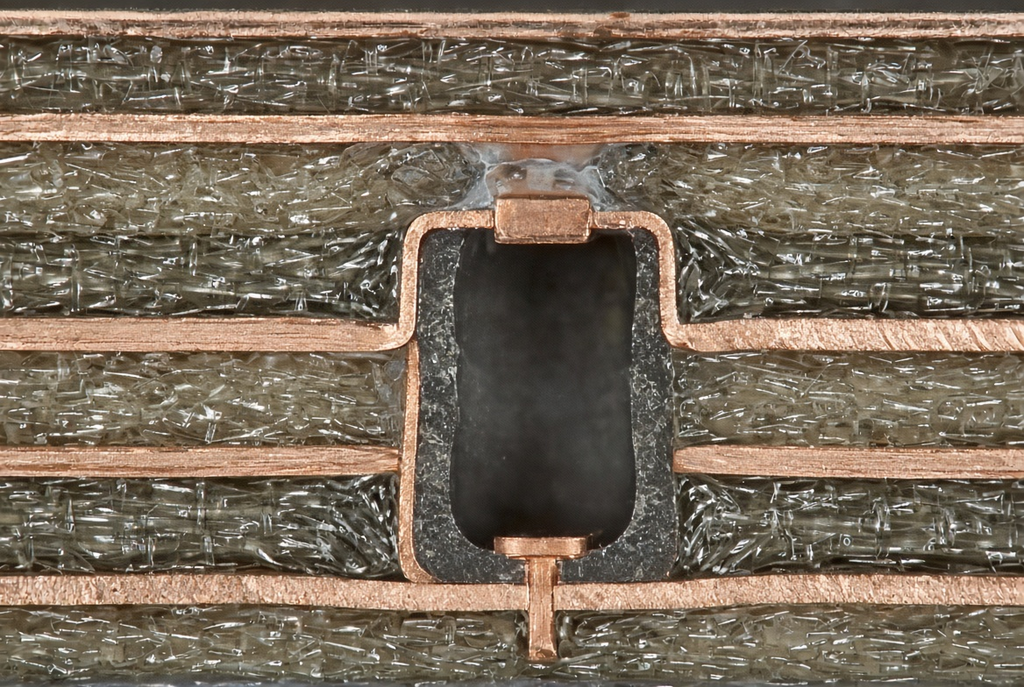
A Pre-Release Checklist for Backdrill Designs
Walk the package and the files as a stack before it leaves the design team. The end result: less engineering questions and less cavities drilled to the wrong stop.
Confirm stack-up, layer transitions, and backdrill targets
Confirm the location of the high speed nets, what layer transitions they use and which remaining vias have a barrel long enough to matter. Note entry side and target layer for each of those vias. Before the table for the backdrill is frozen, make a decision on whether a transition can be moved or replaced by a blind or microvia structure.
This is a pre-flight list, not a slogan. The targets for stack-up, transitions and backdrill should be from the same revision of the drawing. If that package can’t be answered with “which holes, which side, which layer” by a reviewer, then it is not ready.
Align drawing, drill data, and impedance requirements
Ensure that the drawing note is consistent with the drill or backdrill file, that depths do not overlap with reference planes or impedance layers and that all the files in the zip have the same revision. The common case of an updated pair list sitting next to an old depth table is avoided due to a single controlled export, drawing, stack-up, NC drill, backdrill data.
If the plane that whatever impedance coupons or notes take up would cause a cavity to be created, correct this prior to release. The store has a definite package. It can’t handle 3 documents that talk about three different boards.
Frequently Asked Questions
What is PCB backdrilling and why is it used?
PCB backdrilling is creating a secondary controlled-depth drill after a plated through-hole has been created. It is employed to reduce the length of such unused portion of that barrel (via stub) to minimize reflection at high speeds and reduce loss caused by the stub. This is a fabrication step that is programmed into the drill data and drawing notes, and is not a repair in the field.
When does a via stub become a problem in high-speed designs?
Any unused barrel that is long enough, in relation to the data rate and channel budget, will form a stub that will cause reflection or resonance to occur for the link that is not absorbed by the link. This point is dependent on the design. The easy method to determine is to use simulation or a measured reference channel. The term high speed, alone, is not a threshold.
How is backdrilling specified in the fabrication package?
Set the layer or depth for target, the entry side and which vias to include. Enter the same information on the fabrication drawing and the drill or backdrill file (under one revision). A backdrill table/layer-pair callout is easier to understand than a single sentence that reads “backdrill high-speed vias”. Keep-out is in the same package as relative to used pads and relative to reference planes.
Can backdrilling be applied to all vias in a design?
It can be communicated on numerous ways, but not the best engineering option. Every additional hole is a documentation addition, a risk in the process and an expense. Use it at locations where there are no unused barrels that constrain the channel. Don’t use special interconnect vias unless it’s important that they are stubs.
What are the main risks of poorly specified backdrill?
Wrong side, wrong depth, that cavities cut into reference planes or used pads. Vague notes stall the job as the shop seeks clarification. The errors are the same if there are conflicts in drawing and drill files after the bit is in the panel. Impedance copper depths bypassed by aggressive depths are changed to the local stack that the designer released.
Is backdrilling always necessary for high-speed PCBs?
No. Many high speed designs can be constructed on a budget by building up the layers, moving through fewer layers, using microvias, or blind vias—without needing a second drill. Backdrilling is one of the tools available to use for controlling via stubs. It is required only when the unused barrel is proven to be a limiting factor, and the package can establish depth and side sufficiently to build.