A protoboard vs PCB choice is not a battle of the boards, and is more of a decision for the stage of the project. A fast wiring, swaps and one-off bench wiring board with a predetermined hole spacing with basic copper wiring, such as perfboard or stripboard or other catalog boards used for generic boards. A custom PCB is a specific type of board that is constructed with a copper pattern, stack-up, and finish that has been specified and designed from drawings and Gerber data to allow for the same pattern to be laid out and used as a PCB again.
A circuit that works on a hand-wired perfboard is not a production-ready design. Loose joints, long wires, and unplanned return paths can look fine on the bench and then fail under vibration, handling, or noise. Once the schematic is stable and you need boards you can repeat, move to custom PCB fabrication rather than treating the protoboard as the product.
What a Protoboard Is, and What It Is Not
It could be a proto board, perf board, or strip board—whatever you want to call it. You purchase a standard board with a typical hole pattern and a straightforward copper set-up. Most holes on perfboard are on individual pads. Under the grid on stripboard are copper tracks running parallel to the grid, which can be cut and jumped as you wire. Either way, you insert parts into holes and then solder them with soldered wire, component leads or short links.
That’s the purpose of a protoboard when making prototypes. A resistor can be replaced in 2 minutes. A node can be lifted, a test point added or a half analog front end rebuilt without waiting for a new panel. The board is not aware of your enclosure, your connector stack or your noise budget. It provides you with a place to solder.
What it is NOT: a controlled-impedance platform, a repeatable assembly drawing, or a mechanical part that will endure the same shock, vibration and handling as a finished product. The distance from the hole is fixed. This copper isn’t sent back to your return currents. The position of the pad is not equal to the pick and place program. If those are what you need, then you are not at the protoboard stage.
Where protoboards work well
A protoboard pays its value when it’s for learning, not shipping.
Students employ them to determine if a regulator has voltage when the load is changing. A junior engineer uses one to demonstrate that a sensor node wakes up, samples and talks to a host before drawing a board outline. A test engineer constructs a one-off fixture on stripboard because the fixture will never go out of the laboratory and will always be on one test bench. A founder wires a very basic demo so the people at the meeting can see the LEDs flash.
In each of those instances, speed and flexibility are the aims. Enclosure may be made of cardboard box. The ground may be a fat wire that you added after the first noisy capture. No work instruction is currently around pad F14. That’s just using an honest protoboard.
The next situs that causes problem is to remain there because they are familiar with the board. Field trials, loaner units and “just ten boards for the pilot” are not learning experiences. They are riskier but early production.
Where protoboards become a liability
When wiring is done by hand, long paths are produced. A signal meant to be a few millimeters on a custom board, becomes a loop of hookup wire. Current path is taken through as much copper as convenient, not a planned path or a short ground pour. Those loops pick up and radiate noise. The circuit is still “working” on the bench with the short cable and a quiet supply. It doesn’t in a metal cabinet next to a motor drive.
The second failure mode is mechanical strain. A shiny looking perfboard joint is still a small solder fillet on a thin pad with no strain relief on the wire. That joint can crack due to vibration in the vehicle, due to a door slamming against a wall-mounted node or due to repeated connector mating. The same work can be accomplished through temperature cycles, but at a slower rate. Teams then go to the weeks of searching for “intermittent” bugs, which are broken wires.
Inconsistency is the third failure. Each protoboard created from an identical sketch is a different board. Wire length changes. Ground connections move. One hole over is a polarized part. It’s okay for a lab mule. It’s not a good foundation for a product you leave in other people’s hands. It’s a frequent and costly error to send out a stripboard line and then ask yourself why the field returns are so high.
What a Custom PCB Adds
The catalog hole pattern is replaced with a copper pattern you design and the ad-hoc wiring is replaced by the copper pattern. Traces connect to the circuit where they are needed. Pads are located on the footprints as needed. The selection of layers, copper weight, finish, etc. for the assembly process and the environment are not made because they were in the parts bin. The board is not to a standard size protoboard, but to a drawing and fabrication data.
The actual difference between a perfboard and custom PCB is that change. You are NOT purchasing a “green copy” of the same product. From a temporary wiring platform to a manufacturable part.
Electrical and mechanical benefits
Traces can be short, on a well laid out custom board. Pathways can be set up rather than improvised. Switching nodes need not be adjacent to analog sections. A ground strategy can be copper, it’s not the hope of them having thick black wires. The typical improvement in noise and EMI behavior is due to reduced loop area and repetition from board to board.
The same applies to Assembly benefits. The location of the pads is the same on each unit. Connectors line up with the panel cutouts. The standoffs in the enclosure align with the mounting holes. The board and housing can be strained, not a flying wire soldered to a perfboard pad.
There is no automatic way to include that. When you copy it from a protoboard to a CAD tool, you have a custom board that will act like a protoboard, except that the bad routing is now “organized” and permanent. The gains from the electrical and mechanical aspects are derived from an actual layout and a real stack-up that is compatible with the circuit, and not because the laminate is green.
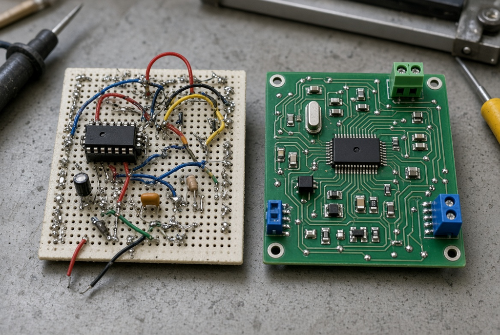
Cost and lead-time reality
A proto-board is an inexpensive and rapid development tool. It is cut, stuffed and powered the same day. The initial board is more expensive for a custom PCB and the first article delay for the fab to check data, make the panel and send it out. The straight trade is that.
When counting past the first unit, the comparison is reversed. The true cost includes some hours rewired on flying wires, a failure that occurred in the field with a hand-built board, etc. For one lab mule, the protoboard will win. The fabricated board is typically less expensive per reliable unit than for a smaller number of pilots required in a single enclosure which need to undergo the same smoke test.
The break-even point depends on quantity, how often the circuit still changes, and how expensive a failure is in the field. It does not depend on a published catalog price for every factory. Before you release Gerber data, use PCB design guidelines to get stack-up, trace, drill, and panel decisions into a package a fabricator can build—not a photocopy of the protoboard wiring.
When to Stay on a Protoboard
Remain on a protoboard during the project in which the question is still “Does this idea work at all?” Learning labs, quickproofs of concept, internal demos that will not ship and one-off test jigs go there. The board is a thinking tool. It is ok to cut traces, add more capacitors and rebuild the power section overnight.
As soon as you start speaking as though the protoboard is the product, that permission is gone! Once you’ve heard the next sentence in the meeting, “we’ll just build ten more like this,” then you’re no longer in the protoboard phase. You’re delaying layout.
Signs you are still in the protoboard stage
Even when the circuit changes daily, you’re still there! You are still there if the “enclosure” is a cardboard box or an open chassis with clips. If 50% of the connections are flying wires to a breadboard, logic analyzer or bench supply then you are still there. If there is no stable schematic long enough to be versioned, you are still there.
Try this: can another person replicate the circuit with the documents you have – without being next to your bench? If the answer is no, then you don’t have a production design. You have a working experiment! Telling people the design is frozen, but the schematic is still a sketch is an overload of words and only postpones the layout work that you already know you will have to do.
When to Move to a Custom PCB
When four things begin to happen simultaneously, it’s time to get off the protoboard: the schematic stops thrashing, a real mechanical plan starts taking shape, more than a couple of identical units need to be built, and it is decided that the hardware will be placed in the hands of others, it’s time to leave the protoboard behind.
There is no need to have a flawless product. You’ve got to have a design that would be stable enough to match the first board with a second board. That’s the time a custom PCB for production or even for a serious pilot becomes an absolute must.
Electrical and mechanical triggers
Electrical triggers are easily felt and ignored. An analog reading is re-triggered when a motor turns on. Radio link fails when touching the ground wire. A reset is displayed when a cable moves. Those are indications of ad-hoc wiring being at its end. Noise, erratic behavior and connections that drop out with vibrations are not characteristics of the personality of the circuit. These are characteristics of the construction technique.
Mechanical triggers are no exception. You are having a true enclosure. Connectors need to align to a panel. The Board must be seated on specified stand offs. Harnesses have a limited length. Now the protoboard is in battle with the box. The first time a field failure occurs, don’t assume it’s your vibration test—it is!
Project-stage triggers
Pilot builds, field trials, certification samples, and any commercial release should all be made using a custom PCB. That board is used to write the bill of materials, the assembly process, and test plan. Polarity, reference designators and inspection points can be recorded. No one can seriously track a process on a hand-wired protoboard which is continually upgraded by many people.
Any parts thru-hole assembly that must be soldered in the same manner on each unit is part of the PCB assembly process, which is typically done on a manufactured board, rather than a line of individuals soldering hookup wire to stripboard. When building on a protoboard it seems to be a through-hole or SMT process, which robs you of the real process questions until the time and money are spent.
Transitioning a Design From Protoboard to Custom PCB
Switching to a clean protoboard to PCB transition is slower on the calendar, but faster in the field. Draw a correct circuit diagram of the working circuit. Don’t assume that the perfboard picture is the truth! Then set your board down once again with traces and returns the same as the schematic, but not where your iron went.
Outline, mount, connectors, stack-up, and finish before you celebrate the first export of Gerber! The Protoboard remains on the bench as a reference and a debug spare. It does not stay in the role of master.
What to carry over, and what to redesign
Bring to the table what worked already: The regulator family that remained cool, the sensor that did meet the spec, the connector that the cable team accepted. If it is still the correct architecture, then include the high level topology.
Refactor the stuff that you were forced to do on the protoboard.Refactor things that protoboard forced on you. For a fabricated board, the following need to be considered: trace routing, ground strategy, decoupling placement and pad positions. The same old noise and old assembly pain can be copied from a perfboard to copper, and is a reliable method for importing. The circuit was demonstrated to be functional on the protoboard.The circuit was built and tested on the protoboard. It did not establish this wiring as the wiring you should do.
Using the protoboard as a test bench
While building and bringing up the first custom boards, the protoboard should be powered up on the corner of the bench. If an unfamiliar board misbehaves, you have a known good mule to compare with it. That’s a proper utilization of the old equipment.
The bad one is the reverse: the only unit that worked is left on protoboard, and the custom board is an add-on. After each firmware update, every customer demonstration and every “quick fix,” they occur on the mule. The fabricated board is not the product. You’ve invested the effort in the layout, and you have retained the reliability risk.
Common Mistakes When Mixing Protoboards and Custom PCBs
The majority of damage in this transition is not exotic. It’s a couple of habits, and they’re the ones that appear to be effective in week three but cost a fortune in month six.
Treating a protoboard as a production BOM
A hand-wired board doesn’t provide a bill of materials. There are no clear part positions. Polarity marks are remembered in someone. A “0.1 µF cap near the chip” is not a separate item that can be purchased twice as a product. You can make an assembly process on that description and you’ll end up with inconsistent builds and debates about which photo is the official one.
Do not write the BOM based on a list of parts that you got off the protoboard at 11 pm.
Ignoring noise and return paths on the custom board
After changing to a custom PCB, noise is not guaranteed to be improved. If the layout is still the long loops and star-shaped afterthought grounding, then the new board can turn out to be worse than the mule. At least the protoboard had a thick wire to move! This is the same error in copper in the fabricated board.
Plan returns along the way of routing. Don’t think that pretty outline and solder mask will do the trick!
Staying on a protoboard to avoid layout work
This is the silent one. The team is aware of the special board that is coming. Everyone agrees. And then some connector changes, another firmware bug crops up, and a demo follows on Tuesday. Spreads another two weeks.Slips two weeks more! In that case, there is no secret behind reliability of protoboard or PCB. The protoboard is being requested to be a product since layout appears like additional work.
This is an actual short-term savings. The long term cost is rework, builds that cannot be repeated, and field units that can’t be reproduced should they fail.
A Simple Decision Checklist for Protoboard vs PCB
Answer these before you decide to stay on a protoboard or move to a custom PCB.
- Is there a stable enough schematic to be versioned or does it change daily?
- More than one or two units which act in a similar manner?
- Is there already some noise, loose connections or vibration on the bench mule?
- Is there any real enclosure, mounting plan or connector location that the board has to hit?
- Will this hardware leave the lab, going into field trial or pilot customer or commercial release?
- Is it possible for a second person to build and test the circuit using the documents you have today?
If the bulk of the responses still revolve around learning and one-off bench work, then stick to the protoboard and keep the pace brisk! If the majority of responses include repeatability, mechanics, and other people’s hands, begin the custom board. Once you have your schematic completely finalized, redo the routing, save the mule as a reference, and don’t expect a generic hole grid to behave like a manufactured product, seems like a documentation and layout problem to me.