PCB laminate materials: The material that is used to carry copper and is responsible for the heat, frequency and mechanical stress response of a board. FR-4 is the standard board material used in many digital, industrial and consumer applications but is no longer regarded as safe for all applications. Projects are driven to high-Tg, high-speed, high-freq., high-flex or metal-core.
All of these are examples of the common error of treating each laminate as “FR-4 with a different label” which results in warped panels after reflow, loud high frequency traces, flex copper that cracks open and modules that get hot and fail to cool. Each Family has their own issue. This guide matches those families to real world application requirements of hardware engineers, PCB designers, NPI teams and purchasing to help prevent late surprises.
Standard FR-4: When It Is Enough and When It Is Not
General purpose rigid boards are made with the standard FR-4 Rigid Board (glass reinforced epoxy laminate board). It is widely used, readily understood by fabricators and assemblers, and is usually one of the least costly rigid solutions available and offers most, if not all, of the day-to-day electrical and mechanical requirements. It’s that combination that many consumer products, industrial controllers, and IoT modules are designed for.
One thing needs to be understood is the word “standard”. FR-4 is NOT a single grade, it’s a family. Resin systems, glass styles and copper foils are dependent upon the supplier of the construction. The constant is the job – simple, flame resistant, relatively inexpensive, relatively high temp, relatively high frequency, product. The combination of all three is still not illogical to start with FR-4.
Typical Use Cases for Standard FR-4
In most low to moderate layers (2-10) digital board, non-critical analog circuit, most power-supply and LED-driver boards, and most consumer applications in indoor or mild industrial environment where cost is a factor, standard FR-4 can be used. Sufficient can’t be the same as “the board powers on. This allows for the normal FR-4 construction to operate at the temperature, assembly profile, tolerance of the impedance, and expected lifespan.
The most common FR-4 job is a 4-layer I/O board with low speed industrial I/O, 1 lead-free reflow and a hermetically-sealed enclosure. So is a consumer control board that is only subjected to thermal shocks on a single occasion and by no one who is in the room. However, this adds to the cost and sensitivity of the process, and it is not an investment in reliability that can be quantitatively determined in the field.
Where Standard FR-4 Starts To Struggle
If the use of a material is routinely outside the thermal and/or electrical comfort limits in the design, consider something beyond FR-4. Most common sources are numerous lead-free reflow processes, ambient temperature at the product mounting site, thick multilayers where the impedance must be controlled through the stack, high-frequency or high-speed signals in which the dielectric loss starts to become an issue, and products that can’t handle warpage or z-axis expansion after assembly.
If the conditions are real (and not hypothetical) begin the material conversation prior to the stack-up being frozen. If you’re at the next family up, it’ll probably not be an exotic RF or metal core system, it is going to be FR-4. In all other ways boards are easy to make, cheap and not better.
High-Tg FR-4: Thermal Stability for Demanding Assembly and Environments
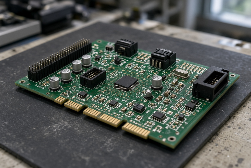
This is still an FR-4 chemistry, but it has been modified to provide some increased ability to handle assembly and service because of the higher glass transition temperature and dimensional stability. It exists because lead-free soldering increased peak temperature in the process and, as more products are being housed in hot cabinets, engine bays or outside enclosures. The copper and glass is still recognizable. It was the change in the resin system that was changed.
The high-Tg is an upgrade to the same manufacturing language, not a new technology for the board. Can be produced by most fabricators on their regular lines, taking care of press cycles, bake and warpage control. Hence, when it comes to a traditionally designed rigid board, FR-4 vs high-Tg PCB is often the initial materials decision.
What Tg Actually Means for Your Board
The glass transition temperature (Tg) is the temperature range over which the resin system switches from a glassy, rigid state to a more rubber-like state. The dielectric’s shape and size is more stable below Tg. As the temperature near and exceeds Tg, the board will also expand, especially in the z-direction (thickness of the board). Any plasticated through-holes below that expansion could fail at some point in time, and, over time, connect with inner layers of the board, increasing the warpage risk during reflow.
The typical industry standard FR-4 grades might fit into a lower Tg range than the high-Tg grades in such applications. Exact values should be found on the material data sheet for the grade that you are purchasing – not as a generic value taken off another supplier’s capability page. What you want from Tg is that it gives you enough clearance from the peak temperature of the assembly and over the service temperature that your board will not change size during reflow and throughout its lifetime.
When to Choose High-Tg Over Standard FR-4
High-Tg FR-4 for lead-free assembly is warranted for applications that require more than one reflow, is thick enough that the z-axis expansion is a reliability concern, has high ambient temperature at product, or has experienced warpage/fatigue problems in the past. Automotive sub-systems, industrial drives and sealed outdoor electronics are examples of products that could be considered “high-tech,” even though the circuit itself is not.
A board that has a single layer of consumer board and is only used once for reflow doesn’t need the upgrade. These are paid for in terms of data-sheet numbers and not field failure, you’d be looking at. For the cases where high-Tg is necessary because of temperature or construction, use high-Tg. If they do not, then skip it.
RF and Low-Loss Materials: Controlling Dk, Df, and Signal Integrity
As clock rate and radio frequency increase, the laminate will no longer be a mechanical carrier and will become a part of the transmission line. Other low loss PCB materials that are specifically designed for high speed applications are engineered to provide a more stable Dk (Dielectric constant) and lower Df (Dissipation factor) across frequency and temperature. Stable Dk: Impedance is fixed. The lower the Df the less energy that the dielectric will take from the signal.
There are still many digital buses that can be carried by FR-4. However, the answer to this comes down to whether or not the Dk variations and loss of the routing length have been included in the budget, after layer transitions and connector launches. Other times, it’s simpler and less costly to replace the laminate instead of redesigning a channel around an item that wasn’t built for that frequency.
Where RF and High-Speed Designs Need Specialized Laminates
Specialized laminates are found on RF front-ends, microwave circuits, radar and sensing modules, communication equipment and high-speed digital links where insertion loss, phase stability or closely controlled impedance are critical elements in the design. These frequencies can cause the loss of FR-4 and Dk as a function of temperature and frequency to close the eye diagram or even to lower the link margin before the layout is finished.
With this, it’s not a post-purchase decision of materials; it’s a signal-integrity decision. All these factors contribute to the stack-up, the form of the copper, the form of the glass and the resin system. If the dielectric is outside the channel you can’t rely on a note on a controlled-impedance fabrication drawing.
Practical Trade-Offs: Performance, Cost, and Fabrication Sensitivity
The cost of RF and low loss systems is normally higher per panel, and is generally more sensitive to handling, moisture and variations in etch or press. Other designs may need a different type of drilling and/or plasma/tempered laminate as opposed to standard FR-4. The materials are not ‘difficult’ because of those facts. They need to be involved with fabricators early.
Before the stack-up is locked, communicate the frequency band, targets for impedance, loss budget, and any desire for mixed-dielectric. In other cases, the compromise is a mixture of FR-4 and a low loss material for the layers that carry the signals. The problem is that a single board is sensitive to only two nets when an all RF construction doesn’t provide any gain in performance, while the material cost and yield increase.
Flex and Rigid-Flex: Mechanical Freedom With New Design Rules
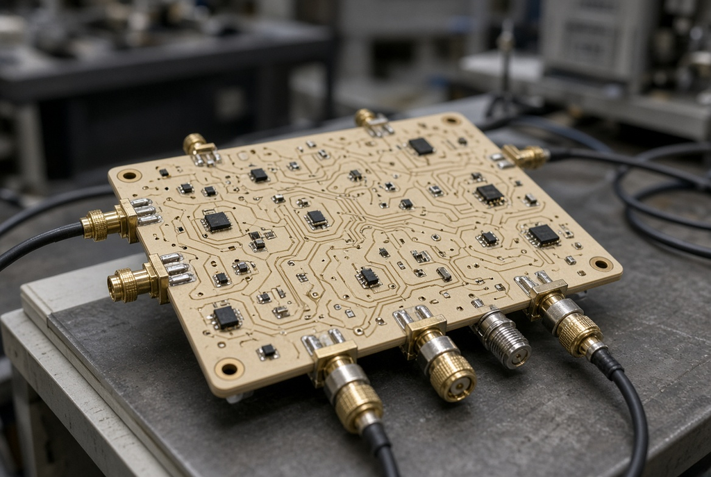
Flex and rigid-flex PCB laminates is another mechanical concept. The circuit may be bent, folded or have rigid and flexible portions in the same construction. This is NOT the “thin FR-4.” Typically a polyimide or equivalent film is used in the flexible areas and the copper, glue and coverlay and stiffeners are chosen for their bend life characteristics rather than for use in a flat panel static application.
The benefits include higher packaging densities and elimination of connectors and discrete cables. Another set of design and fabrication rules is the cost. If a motion, fold-up assembly or 3 dimensional interconnect is not required, a rigid board with meticulous placement of connectors can often be easier and more repeatable.
When Flex or Rigid-Flex Solves a Real Problem
Flex or flex-flex is a specialty that has become a niche in tight 3D packaging, products that flex during use, in assemblies for cable harness reliability or assembly problems and for products that experience vibration or repeated motion in the interconnect. These are generally cameras, wearables, mobile industrial sensors, and lots of tools that are stuffed all in one location.
It is not something that you can style with. Just because a board is rigid in CAD doesn’t mean it is a flex runner. For each of the flexible regions, there are material costs, panelization limitations, and assembly hazards to consider. Be flexible in case of real mechanical problem. Rigid when product must be stationary and linked.
Design and Fabrication Considerations Unique to Flex
Certain of these details are not negotiable, as in the bend radius, bend direction to the copper grain and traces, coverlay or solder mask, stiffener placement, fanning out and holding the board for the SMT process. These flex circuits tend to crack after a few hundred cycles, or after the first cycle of assembly, because the traces bend too tightly, the copper is too heavy to handle the number of cycles or the coverlay openings are at the wrong location.
One more twist is rigid-flex, which refers to the rigid and flexible elements should be designed and recorded, not interpreted or assumed by the fabricator. The two most expensive scenarios of this family of problems is a drawing that cannot be built and an assembled board that fails in the field at the bend; these can be avoided by cooperation on stack-up drawings, bend drawings and assembly fixtures.
Metal-Core and Thermal Substrates: Managing Heat at the Board Level
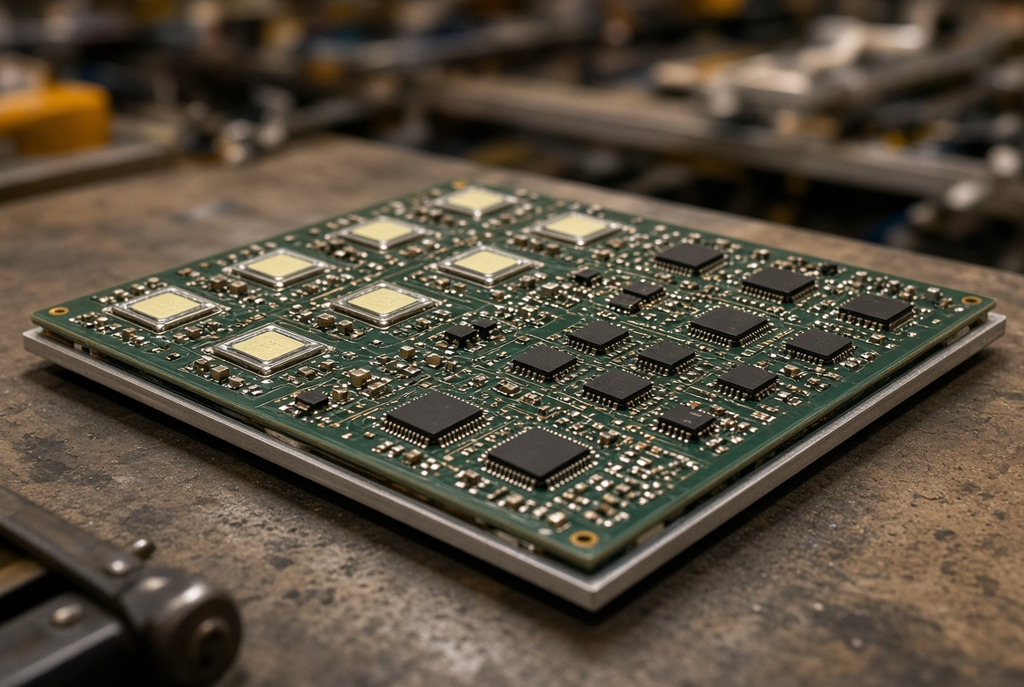
Metal-core PCB substrates are made of a thin dielectric layer that is backed by a metal plate, typically aluminum, but occasionally copper or another metal, through which the heat flows to the side and into a heatsink or chassis. Not the pretty metal back, it’s about thermal management at the board. The standard FR-4 material does not show a very good heat spreading property. If power density at the surface of the board is limiting, then modification of the substrate is more than simply adding copper pours to a standard stack.
Metal-core is one of the other elements of the thermal strategy, which includes copper weight, thermal vias on a traditional board, heat sinks, airflow and device placement. Not for all warm products, it is a particular upgrade.
Typical Applications for Metal-Core PCBs
Common metal core applications include assemblies that contain high power LED modules, small power converters, motor drivers and assemblies where heat is concentrated on the surface of the board. Visible operation against lighting arrays, requiring to maintain the LED junction temperature with the metal base; and against power stages against metal housing.
This is not required in the construction of a low power indicator board. Nor is a digital controller with heat already oozing out of a chassis and a couple of linear regulators. If thermal path across the dielectric is limiting, use metal-core. Be sure to use something simpler if it is not.
Key Parameters Beyond “It Has a Metal Back”
The metal plate is just half the job. The thermal conductivity and dielectric thickness of the circuit copper and the spreader determines the ease with which heat is transferred into the spreader. Weight of the circuit layer has an impact on both current carrying capacity and spreading laterally. That spreading does affect the product depends upon mounting holes, what isolation requirements are required and how the metal face attaches to a metal heat sink.
Even if considering the most obvious uses, the electrical isolation is important. The metal base is not a free ground plane which you can use just like FR-4 copper. Just as watts and degrees go together, so do creepage, clearance and dielectric withstand. NEVER use the metal-core as a replacement for a metal hard FR-4 of the same size. The mechanical stiffness, expansion behavior and the way the stack is assembled differ, as do the ways of documenting the stack.
Common Pitfalls When Choosing a PCB Laminate Family
The majority of laminate issues are not issues with the material itself, but rather issues with the selection of the material. The same three errors occur in consumer, industrial, communications and lighting programs.
Using Standard FR-4 Where Temperature or Frequency Demands More
The most frequent under-specification is for the use of standard FR-4 on a board which is intended to be re-used in a high frequency channel or hot enclosure for a lead-free reflow. Symptoms are known: panels that bow after assembly, impedance that drifts with temperature, insertion loss that isn’t discovered until the finished product is put into service and plated holes that fail before the rest of the design. It may also be “FR-4” and the first articles might be turned on. Cost is represented in yield, rework and field returns.
Over-Specifying Materials When a Simpler Option Would Suffice
The reverse mistake is to use high-Tg, RF or an exotic film in a low-frequency, low-temperature board because it seems safer. Extra-stable dielectrics and low loss systems are more expensive, have a longer material lead time and may add process constraints that the product does not require. The part number was also harder to second-source and the electrical and thermal margins was already good on mid-grade FR-4.
Treating Flex or Metal-Core as a Drop-In Replacement for Rigid FR-4
Flex and metal-core – they are entirely different areas of design. Failure to bend a flex stack by a drawing properly will cause cracking of the copper when copying a rigid FR-4 outline. First, it may be copied onto a metal-core stack of the metal without any dielectrics and thermal interface considerations producing isolation and thermal-interface surprises. Both will alter the way the board is both panelised, assembled and inspected. If the team has not designed that family before, it is a new product introduction of the material system and not just a part-number swap.
A Practical Selection Workflow for PCB Laminate Materials
The choice of PCB laminate should not be determined by the previous project or material brand, but by the use of the application. Documented short-cut design and NPI and purchasing process ensures everyone is on the same page before requesting a quote on a family they aren’t looking for.
Start From Application Requirements, Not From a Material Name
Operating temperature and environment, number of reflow/wave processes to be performed, signal frequency or data rate, loss or impedance stability requirements, mechanical constraints (bending, vibration, 3D packaging), density of thermal materials on the surface of the board, layers complexity & stack complexity, reliability target for product use. The laminate family should be taken off that list.
In the case of only temperature and assembly stresses, a standard conversation is between standard FR-4 and high-Tg. If the system is frequency dominated and/or lossy, consider RF systems, low loss systems, or combination (hybrid) system. Flexible or bendable – flex or rigid-flex options. When heat distribution on the board is the restriction, metal-core is an option. It’s in this way that stack-ups become expensive and still fail to truly capture the risk if the answers are not homogenous and there’s no requirement behind it.
Involve the Fabricator Before Locking the Stack-Up
Know some of the fabrication facts (not schemas): material availability, glass styles, copper foils, mixed-dielectric press cycles, impedance coupons, flex or metal-core process limits. One common reason for revision loops is to send a laminate that is not available or well-documented that is part of a completed stack-up.
Give the requirement list and an initial stack up prior to fixing the layout. Inquire about what the fabricator can repeat, where the construction is sensitive and what notes should be put on the fabrication drawing. Design is under the control of Client. If that authority can be exercised on a stack that isn’t built as intended, then it can’t be kept out of the way due to early DFM input.
Summary Guidance – Matching Laminate Family to Application Risk and Cost
The right laminate family is the one that meets the thermal, electrical, mechanical and heat spreading requirements of the product, but without offering more performance than the product will ever require. The standard FR-4 board is suitable for most rigid boards. Hot assembly & service within the same rigid language, with High-Tg FR-4. If there is a dielectric in a channel, it is possible to maintain the integrity of the signal using an RF system and systems with low loss. Motion/Packaging Solutions for Flat Board.Motion/Packaging Solutions for Flex and Rigid Flex. If the heat blocking part of the board is metal-core, it conducts heat.
Documentation of requirements and comparison of each family with the requirements, with the fabricator’s validation before finalizing the stack-up and quote. That sequence takes some days longer when materials are being moved from the rack at program start-up, and is much quicker than changing materials when the first articles return warped, lossy, cracked, or hot.