When a chip suddenly pulls current out of a rail, the rail goes into a quizzical mode, which is prevented by capacitors on the circuit board. They are used to smooth voltage, filter out noise, and store energy close to the component requiring it. They are represented on a populated board as small surface-mount ceramics, taller aluminum electrolytics, polarized tantalums, or on some analog or power types, film capacitors. All the names are the same. The action is not.
A 470 µF electrolytic capacitor around a CPU power connector is NOT the same as a 0.1 µF MLCC around the CPU in the form of a ring. Just swap them, or you either won’t get a lot of current out of the IC or you lose the bulk reservoir which keeps the input from dropping. The remainder of this article discusses what those parts do when they’re installed in a real board, how to identify capacitor types by markings and package, and what errors will be found when you treat all caps the same.
What Capacitors Do on a Circuit Board
Circuit board capacitors are placed in proximity to a problem: a noisy rail, a load step, a timing network or an EMI path. The physics is just simple charge storage. The helpful question on a board is what time scale and what present that part is supposed to deal with?
Decoupling and local energy storage
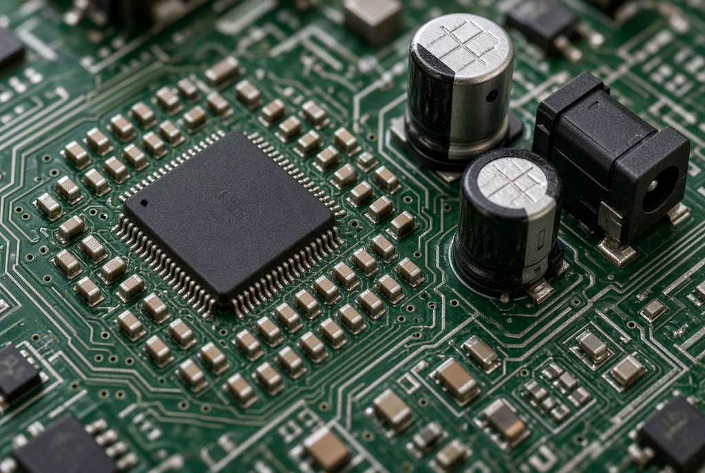
High speed ICs do not draw a smooth DC current. A processor, FPGA or radio chip may require a brief surge from the supply pins before the rest of the board realizes that something is going on. These capacitors are “decoupling” capacitors located on a PCB near these pins, providing that burst of voltage locally instead of causing the voltage to dip and recover in a ring.
This is usually a small ring or group of little ceramics around the part, typically 0.1 µF or 1 µF, occasionally a couple of bigger values thrown in. The loop must be of a short length. Even if the same BOM value is used, a decoupling cap two centimeters away, with a thin trace, does not serve the same purpose.
The one thing it is easy to do wrong is to move those parts to get a clear shot of the logo, test point, connector keep-out and then try to chase random resets. This is a schematic drawing that still depicts a 0.1 µF Cap on all of the rails. The layout no longer places energy at the energy spike location.
Bulk capacitance and filtering
The power input bulk capacitance operates on a slower time scale. A tall electrolytic or a big tantalum close to the barrel jack, USB-connector or regulator output can store enough charge to power a load step lasting milliseconds, not nanoseconds. It also filters ripple that the switching converter or the upstream supply leaves on the rail.
If only small ceramics are connected to the input, then when the board is turned on by a motor, radio burst or the backlight of a display, the board could appear to be “electrically complete” and yet sag. Ceramics have great high frequency. They are not a good replacement to bulk energy if the energy demand is for a prolonged period of time as is not done by the ceramic.
Connect the bulk portion to the current input/output to the board or regulator. Use the small ceramics at ICs, then. That’s why one board can include a 470 µF can and a 0.1 µF of chips, and not be in contradiction.
Timing, coupling, and EMI
Not all capacitors serve the purpose of power. The RC network determines a time constant. A series capacitor allows AC to pass and blocks DC. EMI filter is a type of filter that utilizes capacitance to ground or across a line to shunt out noise. Those components are typically still ceramics, sometimes C0G/NP0 (when the value needs to be stable), sometimes film, in a bigger package on an analog or power stage.
The mistake that can be made here is a casual exchange. When temperature and DC bias change, a capacitor of nominal value C0G is not a C0G capacitor. The circuit is still “full of capacitors. You don’t anymore have the time constant that you calculated.
Common Capacitor Types Seen on PCBs
The majority of the boards you’ll encounter will be based on a short list of capacitor types. Chemistry is important because it affects the package, polarity, surge and the aging of the part on a hot or vibrating product.
Ceramic capacitors (MLCC)
The small rectangular devices on the majority of digital circuit boards are multilayered ceramic capacitors. Common sizes: 0402, 0603, 0805, and larger (1206) are on denser or higher-voltage layouts. They don’t have a polarity mark. These are used by default for decoupling and high-frequency filtering.
Dielectric codes are used to indicate the stability of the part. The typical choice for timing, RF and precision analog is C0G/NP0 which remains stable near its marked value over temperature. X7R has a higher capacitance in the same package, but decreases due to DC bias and temperature. High-K dielectrics, such as Y5V, are cheap on a BOM, but lose a significant amount of capacitance on 5V or 12V.
All ceramics are treated equally and a first power up and a temperature sweep is passed. The two 0.1 uF 0603 may be different parts.
Aluminum electrolytic capacitors
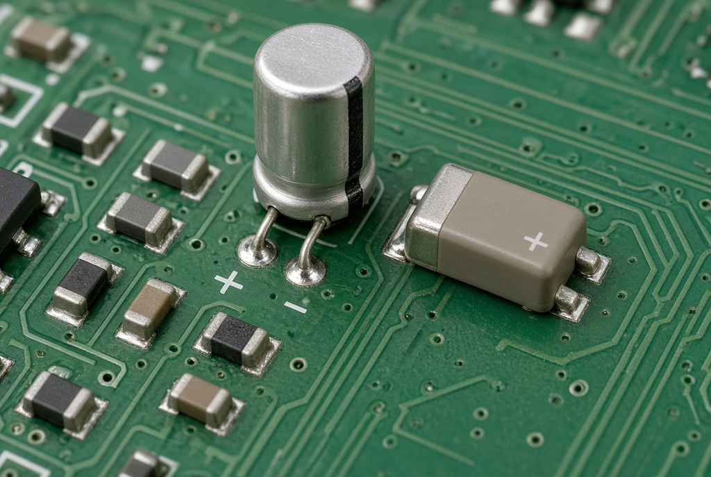
Aluminium electrolytics (cylindrical cans, through-hole radials or large surface-mount packages) are typically located at the power input or a regulator output. They provide bulk capacitance which you could not get from a much bigger ceramic array. They are polarized. Most aluminum assemblies have the printed stripe indicating the negative lead.
The voltage rating and temperature rating are as important as the microfarad ratings. If a transient comes in at a later time, the 6.3 V part will have little headroom on a 5 V rail. A portion marked for a cool bench will dry out quicker than another portion that is next to a hot regulator. The failure is subtle, when it occurs: venting, heat or early short; the reverse of the can is the answer.
Tantalum capacitors
Tantalums are small, polarized chips or dipped through-hole parts that offer the same capacitance in a smaller outline than an equivalent aluminium can. The positive side of a typical tantalum package is the marked end — the opposite as many aluminum electrolytics are — hence the confusion between the two types.
These are helpful if board space is limited and bulk capacitance is still an issue. They will not tolerate reverse voltage or inrush greater than the surge rating. It is a frequent field failure to substitute a tantalum in a high surge input circuit originally designed around a ceramic or a polymer electrolyte. Please read the data sheet for voltage derating and surge limits prior to the swap.
The comparison between MLCC, Tantalum and Electrolytic is not a quality comparison.
Film and other specialty capacitors
Typically, film capacitors are medium-sized and rectangular or boxed in audio signal paths, snubbers and EMI filters. They also are much less common on dense digital boards because they don’t shrink the package like an MLCC does. They tend to be non-polarized and more stable than a high-K ceramic of this quality.
Assume nothing about a large non-electrolytic body being film. A few inches away, some power ceramics, safety-rated Y capacitors and polymer parts look similar. The identification is not the color, but package plus location plus the BOM line.
How to Identify Capacitors on a Board
The package, the markings, and the context: how to identify capacitors on a board. Begin by using what can be observed without a datasheet. When the part is important confirm with the BOM.
Package and size clues
This is a very common situation, where a small, unmarked rectangle in 0402, 0603 or 0805 is almost certainly an MLCC. Aluminum Electrolytics are a tall cylinder with a printed stripe. Polarized small rectangle or molded chip with one end indicated is likely to be a tantalum. An analog or filter section might have a larger boxy body, which could be film.
The size of an object is not a type. There is a polarity mark on an 0805 ceramic and a small tantalum can that make them look alike, but until you locate the polarity mark. Two parts, both of the same land pattern, can have different dielectrics. A repair places an incorrect family on the pad, simply assuming all small caps are the same, that they all have the same footprint.
Markings and polarity
Smaller electrolytics sometimes have a three digit code or simple text such as 100µF 25V. 106 in that system is 10 × 10^6 pF, which is 10 µF, not 106 pF. The voltage can be a single letter or printed voltage marking that is not an included part of that code.
The marking that really saves boards is polarity. Electrolytic strip of aluminum: negative. Tantalum bar: Positive on the typical SMT packages. Ceramics: no polarity. If there is a conflict between silkscreen and part family, stop and verify the footprint and the BOM before soldering.
The capacitance number is all that’s required to calculate the voltage, and one of the other two numbers is required to calculate the voltage, and the other two are required to calculate the voltage–a “matching” replacement still fails, unless one is careful enough to read the capacitance number only, and not to consider voltage, dielectric and polarity.
Context on the board
Placement is the fastest sanity check. Caps clustered at IC power pins are likely decoupling ceramics. Caps at the power connector or regulator output are often bulk electrolytics or tantalums. Caps in an analog filter or RF matching network may be C0G/NP0 or film. Color is a weak clue. Package and location are stronger.
Once package and polarity are clear, the remaining question is how those parts will sit on the pads. That is the work of PCB assembly — surface-mount placement for the small ceramics, through-hole or mixed process for many electrolytics — not a substitute for reading the component itself.
Capacitor Choices and Assembly Reliability
Capacitor packages and assembly are linked because the same part that solves a noise problem can crack, reverse, or dry out if the package was chosen without the build and the environment in mind.
SMT size and handling
Very small MLCCs need accurate placement and a controlled reflow profile. They tombstone, shift, or crack when the pad design or the thermal ramp is sloppy. Larger 0805 and 1206 bodies are easier to handle and inspect, and they take more board area. Mixing 0201 and 0805 on the same design is possible; it is not free. Rework tools, stencil design, and inspection all change with the smallest part on the board.
Do not treat a tiny package as a default cost cut. If the assembly house or the prototype bench cannot place and inspect it consistently, the electrical benefit disappears in yield.
Polarity and orientation
Electrolytics and tantalums have one legal orientation. The footprint, the silkscreen, and the BOM must tell the same story. A land pattern that is electrically symmetric but visually ambiguous is an invitation to place the part backwards on a rushed line or a late rework.
Check the positive mark on the tantalum against the “+” on the silkscreen. Check the negative stripe on an aluminum can against the board marking. If those two disagree, the CAD library is the problem, not the operator.
Thermal and mechanical stress
The board can cause the ceramics to crack in the event of a sudden thermal shock or bending or flexing. This risk is greatest near connectors, mounting holes, and edges of the boards where the laminate flexes. A “good” decoupling network can suddenly become noisy after dropping or press-fit connector, because of a failure of the MLCCs in the network, either open, short, or intermittent.
In hot enclosures, electrolytics leak electrolyte with time. A correct ESR on day one can go “haywire” after a couple of months in a power FET’s vicinity. Another failure mode of large radial electrolytics is from vibration, which can occur at the lead or at the can seal. The capacitor family is part of the design review, even when the only column that has value is the microfarad.
Common Mistakes When Reading or Replacing Capacitors
Most capacitor mistakes are substitutions that look harmless on a BOM line.
Assuming all caps of the same size are equal
The real capacitance on the rail can be reduced by replacing an X7R with a Y5V with the same case size and the same mark. A change from a C0G to an X7R in a timing or RF circuit will cause the frequency or filter shape to shift. There is still a 100 nF piece left on the board. No longer the same part.
Match dielectric, voltage, and package family, not only the number in the schematic.
Ignoring voltage rating and derating
The simplest way to pick a capacitance and assume it will just survive on a 5 V rail is to pick the capacitor with a voltage rating of only 6.3 V. There is also a decrease in the effective capacitance of many ceramics due to DC bias, and a part that is “10 µF” on the reel may not be that on a 12 V node. The same goes for temperature rating. In a closed box, a 105 °C electrolytic and an 85 °C electrolytic are not the same.
Reversing polarized capacitors
Reversed electrolytic or tantalum can can heat, vent or fail short. The silkscreen is not necessarily correct. Verify the CAD pad, body polarity and the BOM description before taking it for granted that the board art is correct. One backwash with a power input can do the trick and ruin the first article.
A Simple Identification Checklist
Walk this order of the part before naming a type or approving a substitute:
- What is the package’s size and form? Small un-polarized chip, high can, marked SMT rectangle or larger boxed body?
- Does it have a polarity mark and if so, is it a negative mark (typical aluminium electrolytic) or positive mark (typical tantalum)?
- In which power pin, power input or power regulator output, an analog section, timing section or EMI section?
- What does the marking really indicate with regard to capacitance and voltage—even for three-digit values like 106?
- Is the dielectric and voltage rating of the BOM the same as the part you believe it is performing the task?
Now use those clues first! There is only one schematic value field. If you consider package, polarity and placement together, the board will tell you the rest.