Printed circuit boards are found in all situations where electronic components are required to be located and linked in a repeatable item. It’s all the things from industrial controls, consumer electronics, sensors, network gear, lighting modules, robotics and test gear. The question “What are PCBs used for?” is not a yes or no question. There is a board in nearly all electronic products. The question is, which constraint does this product impose on the board: density, layers, heat, flexing, impedance, current, or a hard cabinet?
A compact battery device, a high-speed network card, and a higher-current drive do not ask the factory for the same stack-up, copper, or assembly process. One standard green board does not cover those jobs. Readers matching electronics industry applications to fabrication, assembly, and inspection should start from the product, not from a generic board type.
Industrial Controls and Automation Equipment
The answer to what are PCBs used for begins in the cabinet. Boards featuring a combination of parts and ensuring those connections are stable after the first article are essential for programmable controllers, motor drives, sensor interfaces, power supplies and operator panels. The mechanical board and the assembly must be planned together for three reasons: Vibration, Cabinet temperature and Connector load.
A PLC Backplane is NOT a small analog sensor card. In addition to surface mount logic, the controller typically features through-hole connectors, through-hole terminals, and larger passives. The sensor interface can also be a small board that has a very short connector pitch and not so much space for test pads. Adding a drive or power-supply board will add current paths to heat around switching parts. Industrial control PCB applications are still divided between those constructions. While it is true that all of them are an industrial PCB, it conceals the difference.
Repeatability matters as much as the first working sample. Cabinets are serviced, firmware is updated, and the same assembly number comes back months later. If polarity marks, connector callouts, or revision notes lived only in someone’s email, the second build is a new negotiation. For teams building industrial automation electronics, the product class is only the starting point. The factory still needs a documented interconnect, a mixed SMT and through-hole plan where those parts exist, and inspection that matches the actual board.
What the factory actually has to get right
An industrial label is not used to specify copper weight, coating or test coverage. These decisions are based on the drawing, the current, the environment, and the agreed upon inspection plan.
A build package should be what the factory has to hold, which consists of a revision that matches the files, a BOM that matches the centroids and polarity marks, and a note indicating what checks apply to this assembly. Various tests are performed on that package: an incoming board inspection, a solder-paste check, an optical check, and a final visual or electrical check. They’re not an assumption of the term “automation.”
The usual error is the use of the term “industrial control equipment” as the specification. That is describing the cabinet, not the copper, the hole schedule or even if there is any extra protection needed. When an engineer, wrote down what was watched, if the first article passed. If not, the next lot is constructed from memory.
Consumer Products and Compact Connected Devices
There’s a lot of pressure and a lot of no room for consumer products and small connected devices. They don’t have the same board problem.
A remote, a handheld instrument or small appliance board is typically evaluated on cosmetic finish, panel yield and repeatability at volume. Open housing reveals edges, legend and surface finish. A harmless (unaffecting) lost polarity point turns to a field return when the board is exposed to the operators or when the board is built quickly in a steel cabinet.
There are other limitations, such as battery-powered sensors and compact wireless products. After the industrial-design freeze there is little room for moving parts due to antenna keep-out, battery outline and button position. Low-power layouts also allow for less leeway if package height or RF behavior changes with a substitution. The same products are still printed circuit boards – just different. Unordered as a Consumer Display board where only a clean Face and a constant BOM is needed.
Please do not use this section as a market survey. Manufacturing question is whether it’s asking for cost and finish or asking for small radio and battery that needs to survive a specific outline.
Density, outline, and the bare-board limit
A small enclosure often forces a denser layout, a tighter board outline, or a flexible section that folds into the housing. That is a construction decision, not a decoration. If the product needs a bend, say so and show the bend region. If it only needs a smaller rigid board, do not ask for flex “just in case.”
PCBs for IoT devices inherit the enclosure and the radio first. The bare PCB still does not make the product work. Parts, firmware, and a test plan do. Sending an enclosure render and expecting a fabricator to infer the board is a common stall. The factory can check outline, hole positions, and stack-up against the mechanical file. It cannot invent antenna placement, button travel, or a functional test from a product photo. Teams building IoT and smart-device electronics should send the board constraint with the files, not only the product name.
State the deliverable. A bare board with a controlled outline is one job. An assembled, programmed, and tested module is another. Compact products fail in purchasing when those two jobs are written as one line item with no files for the second.
Communications and Networking Hardware
Switches, radios, and interface cards change the fabrication conversation. More layers, a planned stack-up, controlled impedance, and consistent geometry show up because the signals on the board are no longer “just connected.” They have a target path.
Controlled impedance, in plain terms, means selected traces are built to a stated resistance so high-speed signals behave as the designer intended. That only works if layer order, dielectric, copper weight, and trace geometry are written into the fabrication data. A note that says “high-speed” without those targets is a warning flag, not a build instruction.
Communications and networking hardware therefore needs a different review than a two-layer control card. The buyer does not have to teach signal-integrity theory. The buyer does have to supply impedance targets, a stack-up direction, and material notes the factory can check before lamination. If those items are missing, a capable factory should stop and ask. Guessing the stack-up after the cores are pressed is how a pretty board fails in the chassis.
What “high-speed” changes in the order
A high-speed callout changes what belongs in the order packet. Layer count is not enough. The packet needs the intended layer order, which pairs carry impedance, the target values, and any material family the design assumes. Via style and back-drill notes belong there when the layout uses them.
Geometry consistency matters as much as the nominal value. Two boards that both say “50 ohm” can still differ if etch, dielectric thickness, or reference planes wander. That is why the factory should question gaps in the data before pressing the stack, not after the panels are routed.
Do not treat a website category as a substitute for those numbers. Networking equipment PCB requirements live in the fabrication notes and the stack-up drawing. They do not live in the product name.
Power, Lighting, Robotics, and Test Equipment
The uses are grouped together because they all modify a physical demand. They’re not four additional market paragraphs.
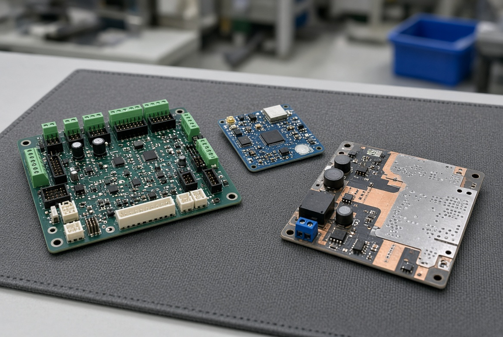
Power electronics and lighting increase the current and the heat. A converter, a driver or an LED module that is running watts through the board is begging for a thermal path—more silkscreen. The controller, the sensor interface and the motion-power stage are combined in one machine in the form of a single assembly or multiple separate assemblies, as is the case with robotics. Test equipment requires stable measurement paths, disciplined revisions and access to test equipment for checks. Lighting and power electronics, motion and lab equipment will be specified by their intended functions, such as those involving PCB.
Heat and current are specification issues
May require metal core construction, heavier copper or other path way from the hot parts to heatsink or chassis for an LED module or a higher current board. A metal-core is a metal plate within the board, which conducts heat. The thicker the conductive layers, the more current. This is not an automatic upgrade!
It will depend on the thermal design and on a process that a fabricator has the capability to perform. If it is a lighting board with a simple rigid structure, it remains on this type of structure. If the power stage is overheating on a thin two-layer card, it’s going to be a problem regardless of what color the mask is. Record the current, the temperature increase expected and any existing note in the design that is made of metal core or copper. Never request the factory to create a thermal stack for the product category.
Stay away from long, low lighting cases. Heat and current are the two problems of the board. It is not a request to change the LED materials list.
Motion equipment is more than one board
A robot or an intelligent machine does not generally exist in just one stack-up. The motion controller can be an industrial logic board. The sensor interface can be small and densely populated with connectors. The power stage could be high current and require other copper or clearance. The outline rules of those assemblies may be different, the risks of mixed technologies may be different, and the inspection plan may differ.
Requesting a “robotics PCB” shortcuts that set to one imaginary part number. Send the board on the bench: Controller, interface or drive. If multiple boards are ordered together, mark each board. The mistake is considering the machine name as the construction.
Test equipment is an additional discipline. Precision and revision control is important because a future lot might be evaluated as a comparison with an earlier measurement. Probe access, guard traces and connector wear are visible on the layout. Some files are still required for the factory, as well as a declared build phase. Lab instrument is not a stack-up!

Uses That Need Verified Experience, Not a Generic Claim
Printed circuit boards are found in real products such as automotive electronics, medical devices, energy or power-conversion products. There is still a need to fabricate a board and, in many cases, assemble a board for a vehicle module, a patient-side instrument, or a converter in an energy system.
This is not to say “there already is a factory that serves this market.” Project requirements include safety, traceability, process control and certifications. They’re not tags that a website category can add. The buyer should inquire what work the factory has actually completed and what are the documents to prove the work. These are examples of the sectors that can be applied. They do not guarantee any particular manufacturer to be experienced or approved, including CKS Circuits.
Never assume that capability is based on the page title. When the product is used under a regulated or safety critical use, evidence must be provided from the project file, quality plan, and be supported by the factory’s records. The sector name is for the end product, not the supplier’s qualification; until those items are checked, proceed as if it is a product name and not a completed supplier qualification.
Questions worth asking before naming the sector
Prior to a quotation being categorized as a service to the automotive, medical, or energy industries, ask a few questions about the manufacturing process:
- Has the factory constructed boards of similar construction, density and assembly mix and is it able to explain that work without calling out restricted customers?
- What are the inspection, traceability and record-keeping requirements for this build, and what are those that are only required if they are included in the order?
- What are the standards or customer documents that need support that are not being supported with a brochure line?
- Which of the following CAN NOT be assumed from an industry heading: coating, test coverage, change control or a cleanliness requirement not specified?
If answers are brief, maintain the order description technical. Give the board and the environment a name and give the checks names. Do not put the sector badge on the purchase order until evidence is available.
How to Turn an Application into a Buildable Request
The application is only useful if it conveys the constraint to the factory. Environment, speed, bare board vs. assembly, current, flex, volume stage, and heat all impact the construction of a PCB with application. “Used in industrial equipment” is not a request, if it is not accompanied by a drawing, no layer count information provided, no statement of assembly. It is a category.
Attach the context along with the files. The reviewer has some thing to check: Gerber data or other fabrication data, a short description of the product, and the limits to the board which are affected by its environment or its electrical operation. Include the build step: prototype, first production article or locked revision. Include BOM, polarity and any existing test instruction, if applicable, if components and assembly are in scope.
CKS Circuits is a Guangdong PCB/PCBA partner provides PCBs/PCBAs fabrication, component sourcing, assembly, inspection, test, prototype to repeat production services. That’s still up to the packet you pass. Any application note that is accompanied by a full set of data is usable. A market label plus an incomplete zip archive isn’t.
State the board problem in one sentence before you send the folder. Vibration and mixed connectors for the cabinet. Tight wireless outline and a battery. Layers for an interface to a network, wherein the layers are impedance-controlled. Lighting or power stage heat, current detection. Isolate the controller and drive boards of a machine. A sentence like that is what makes modern electronics products containing PCBs manageable for the factory.